PCB Manufacturing
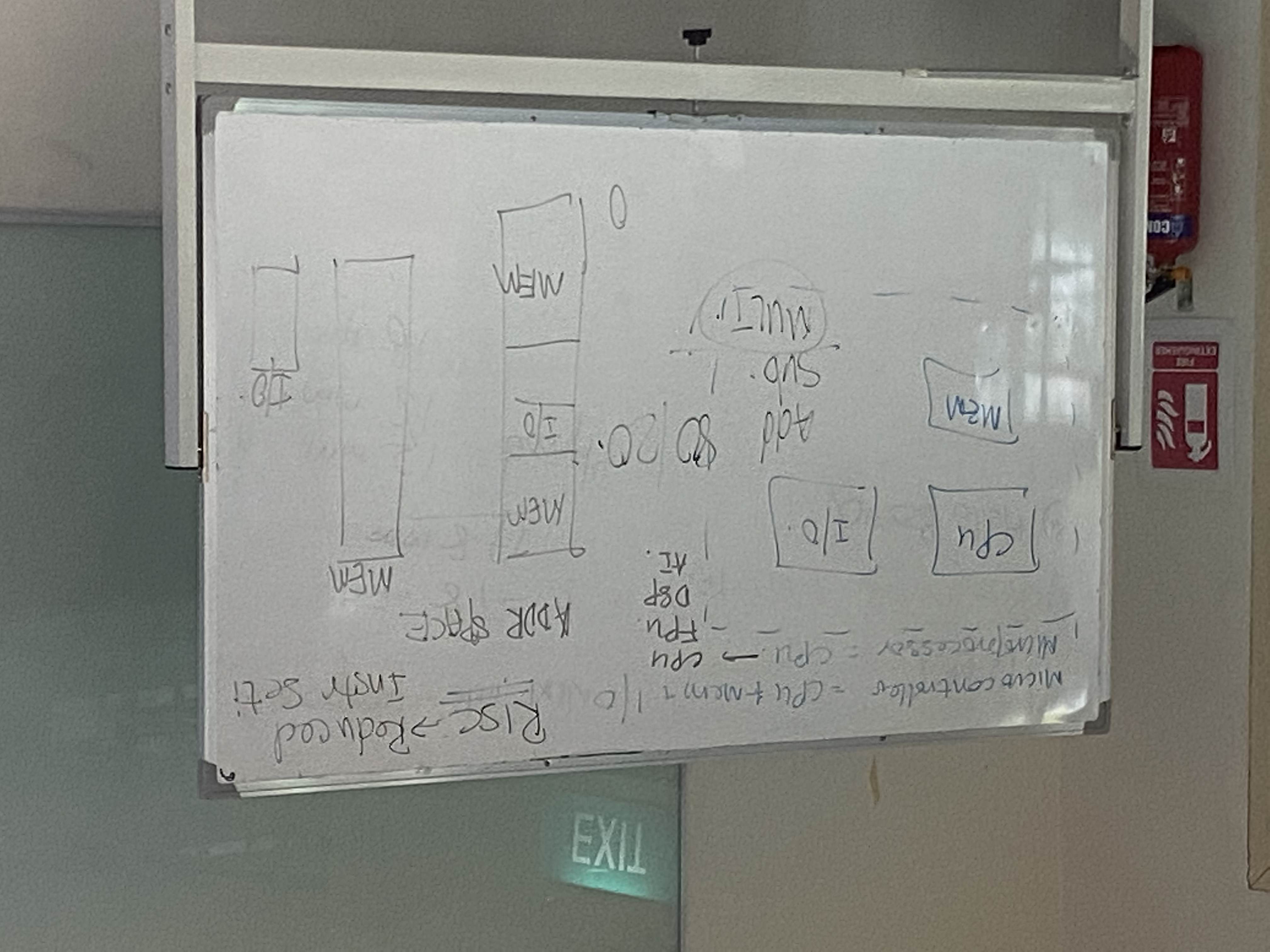
Micro controller vs Micro Processor
Making of FTDI to UPDI programmer
"Typically, debugging via the serial monitor and burning the bootloader requires 2 connectors: FTDI and UPDI (like the ICSP connector for the Atmega328 and others) These connectors, however, take up a lot of space on the pcb, especially with respect to the fact that the ATtiny devices, such as the ATtiny3217, are very small. That is why a combined FTDI / UPDI connector would help take less space on the pcb." -Sauce
Using a universal FTDI to UPDI boot loader, we can compact our microprocessor board and have only the essentials on the board.
For the first two board, we made a FTDI and UPDI programmer board.
The FTDI has a transmit and receive pin (tx & rx), and a VCC and Ground pin. The UPDI pin burns the bootloader into the UPDI pin on a UPDI microcontroller.
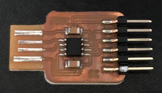
FTDI example
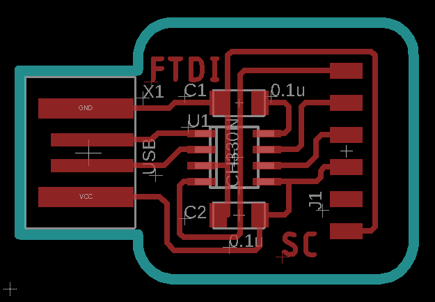
FTDI Wiring on EAGLE
UPDI example
Using the png files provided, we loaded it into mods to obtain a Gcode file.
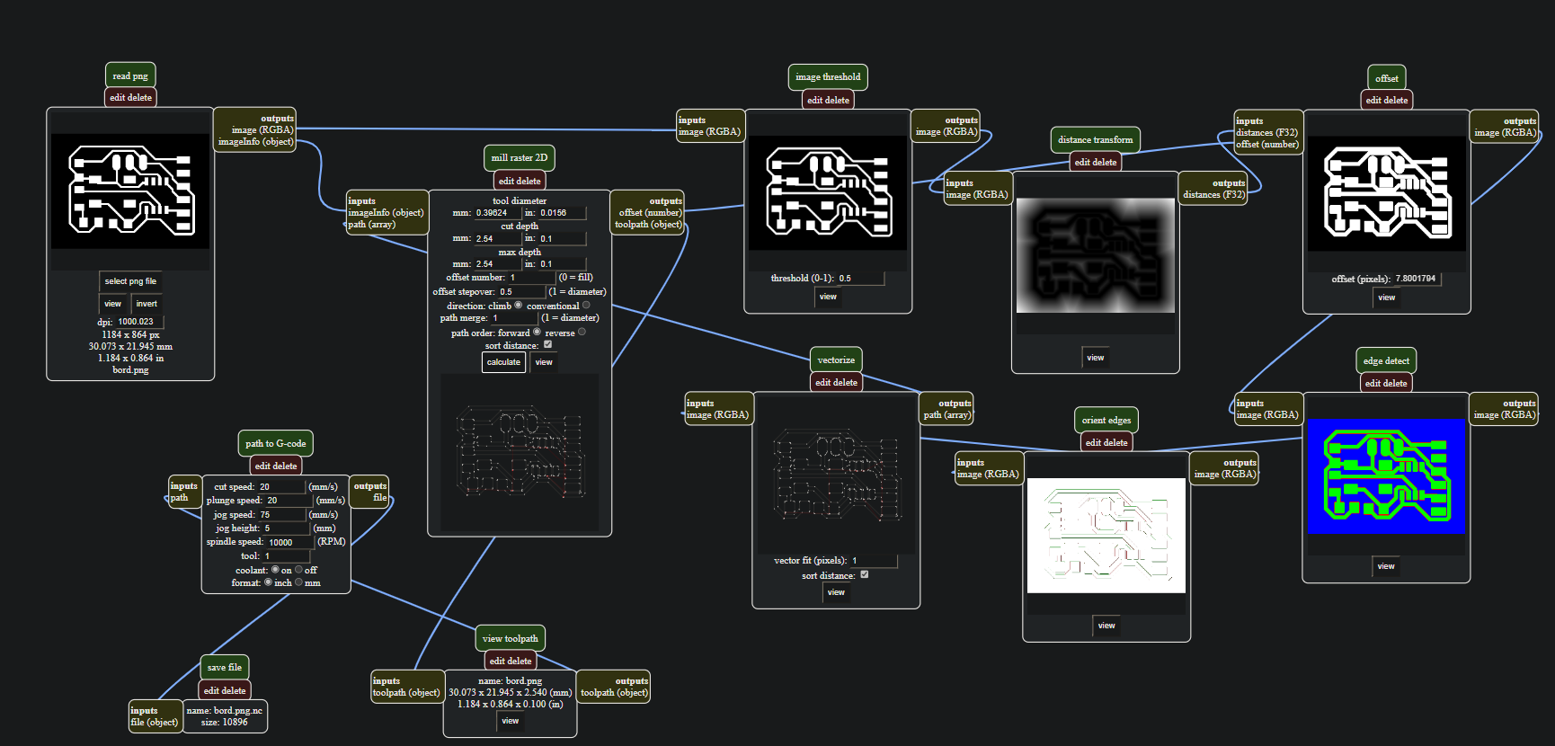 Open mods and right click : menu/ programs/ open server program/ mill 2D png.
Then, "select PNG file on the left", load the png.
Under 'Set PCB Defaults', select either the traces or outlines preset parameters.
Afterwards, under 'Mill Raster 2D', click calculate, and the Gcode will be generated.
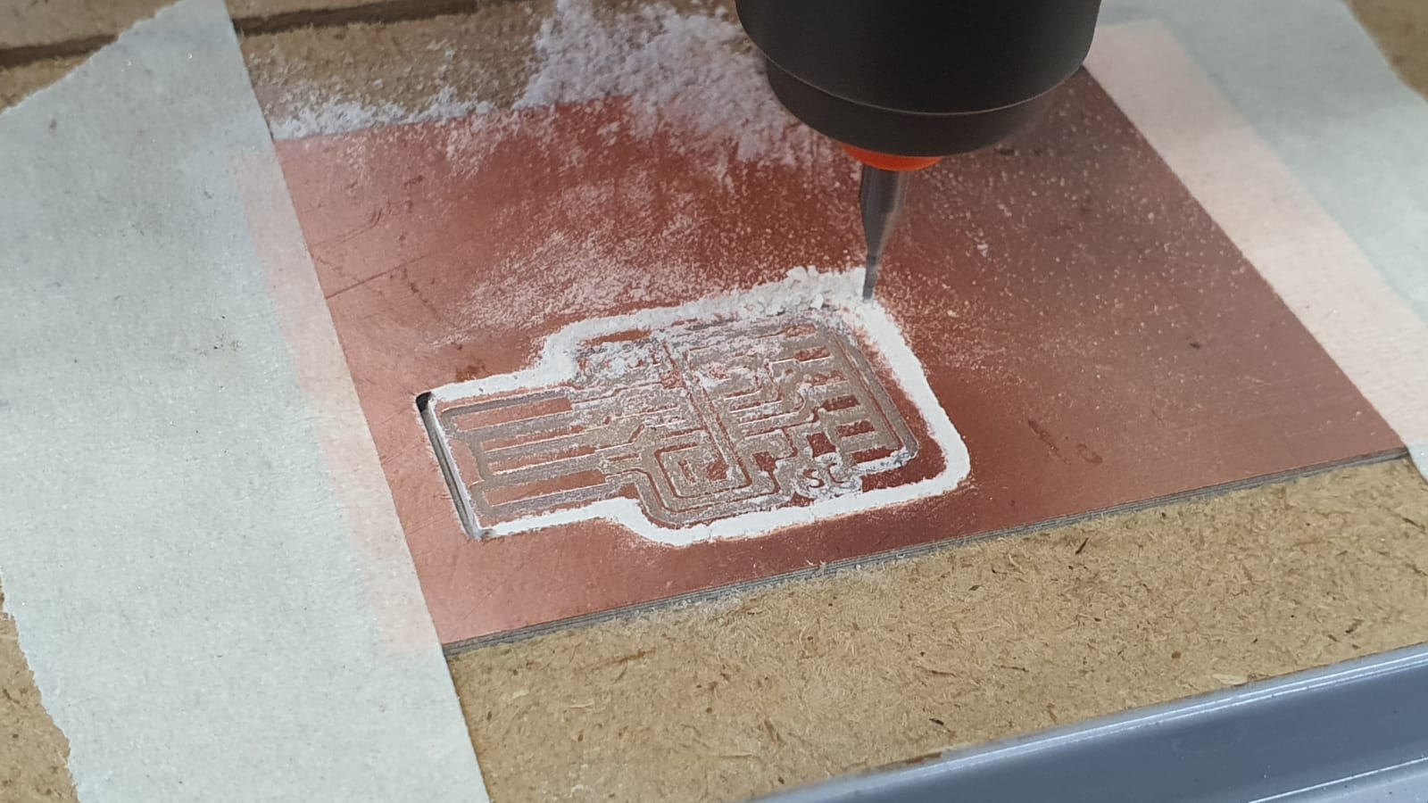
After that, we uploaded the gcode file into the computer on the CNC Router.

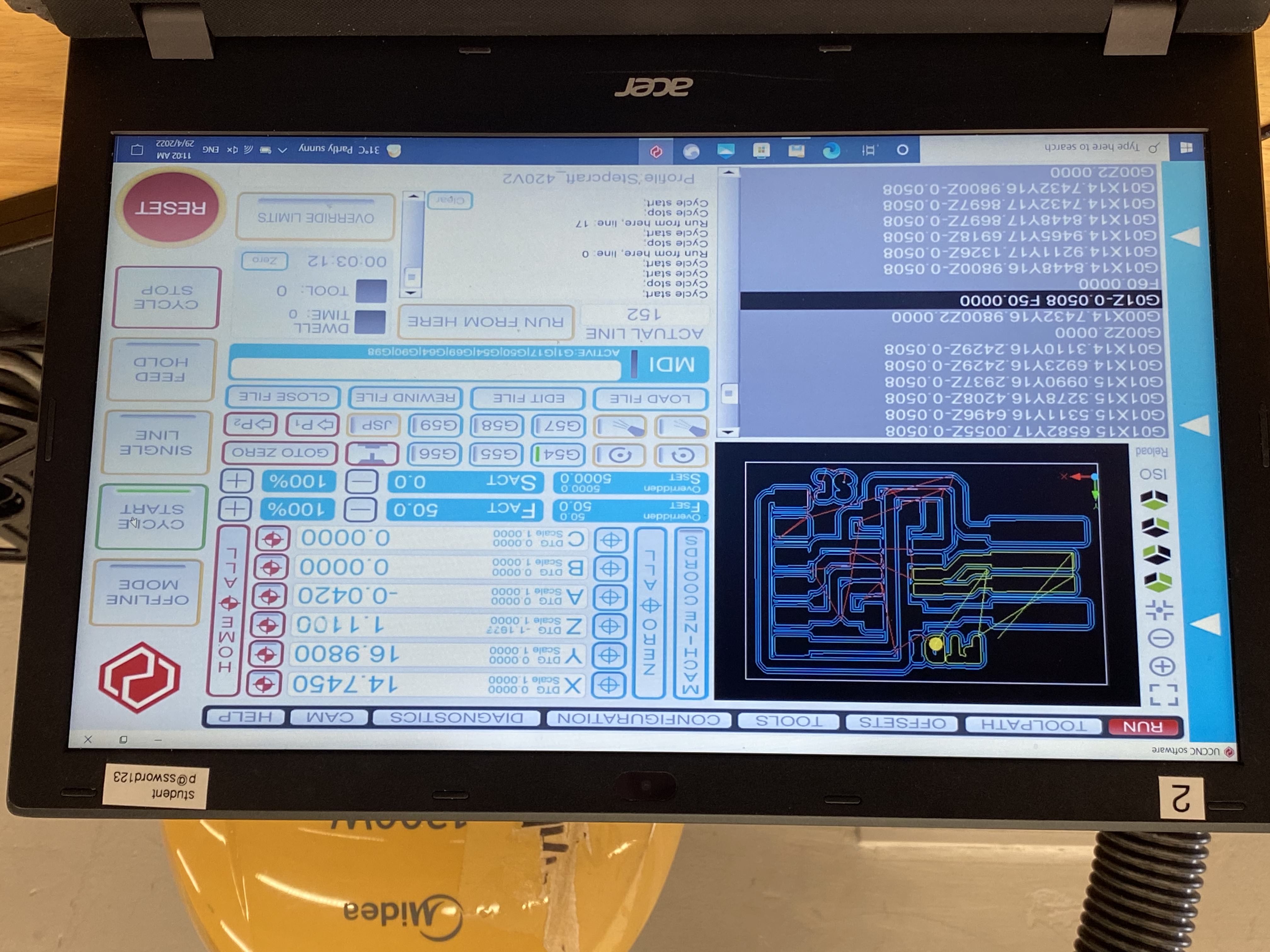
Then, we set the X and Y coordinate to 0 on our prefered start location, and set the Z to 0 using the "Zeroing Tappy Tappy" (a micro switch with a zeroing sensor).
During the routing process, the adjustment of the Z axis is favourable when it is undercutting or overcutting, so increasing or decresing the Z offset will yield better cuts.
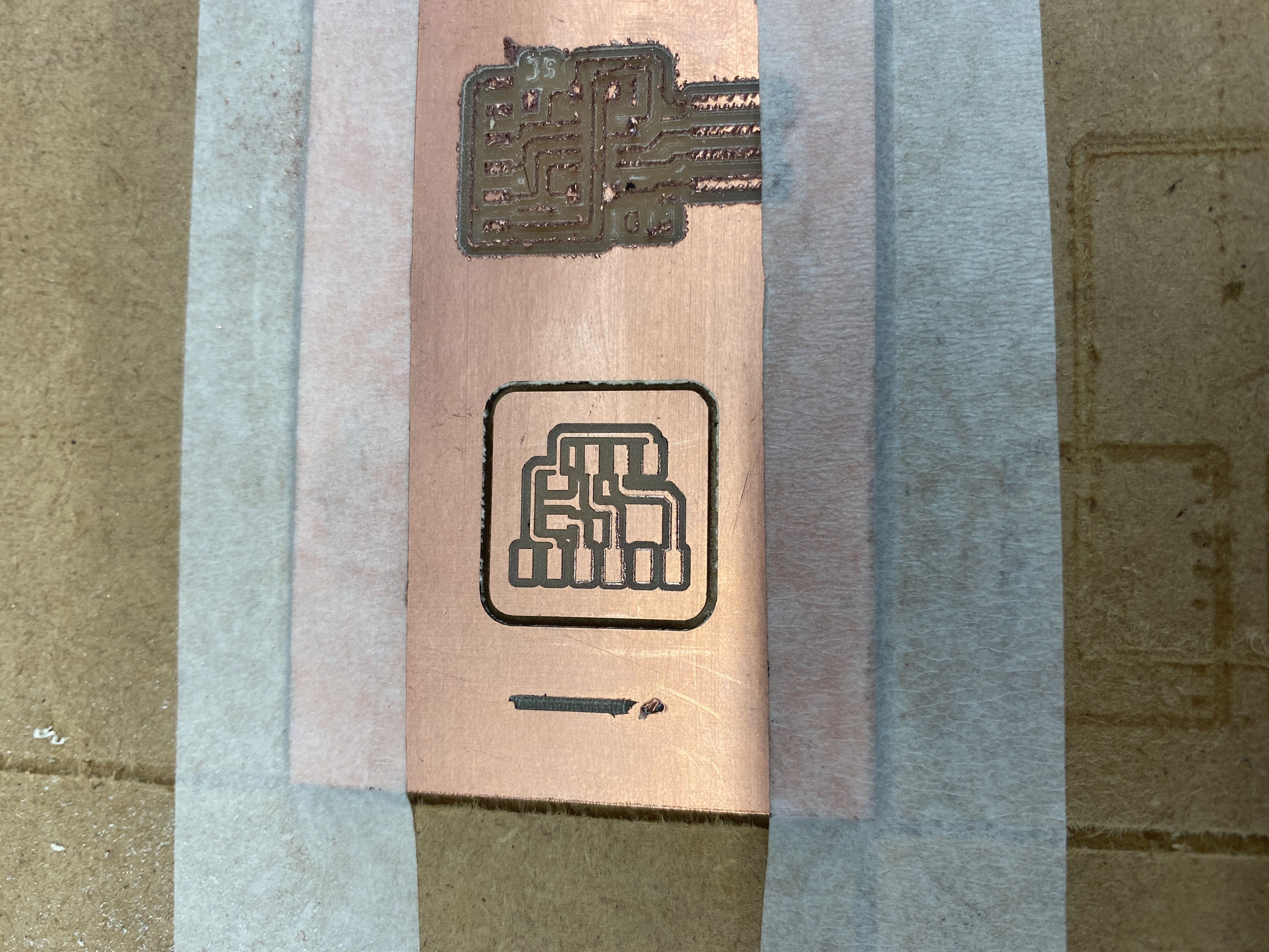
In process of routing FTDI
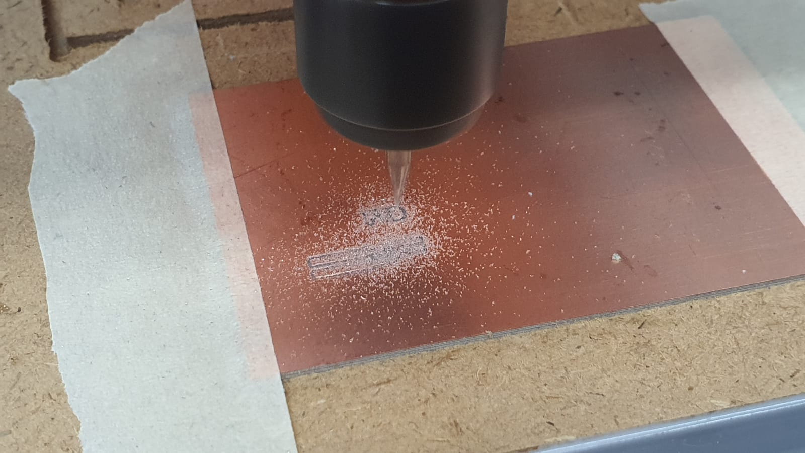
In process of routing UPDI
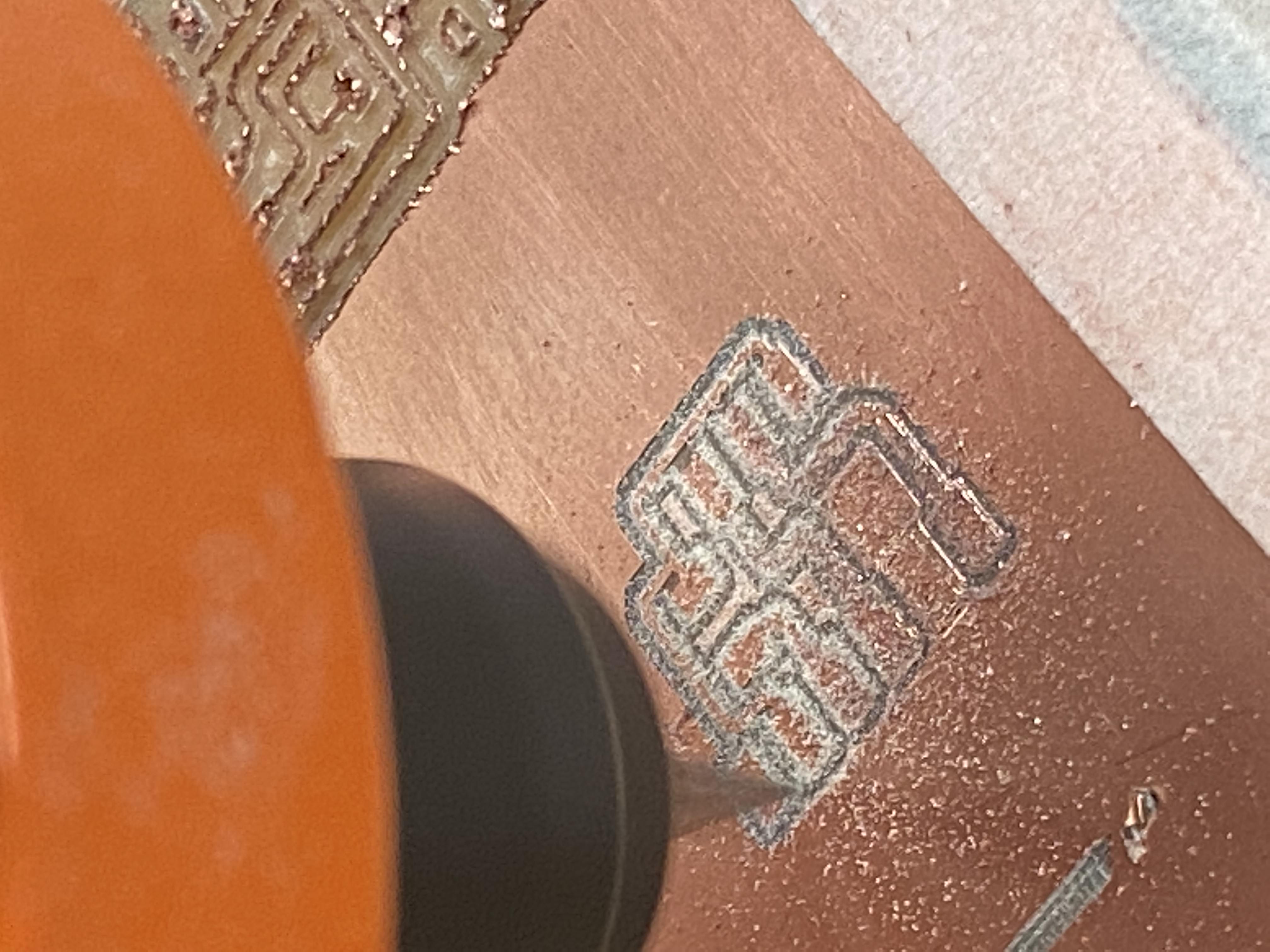
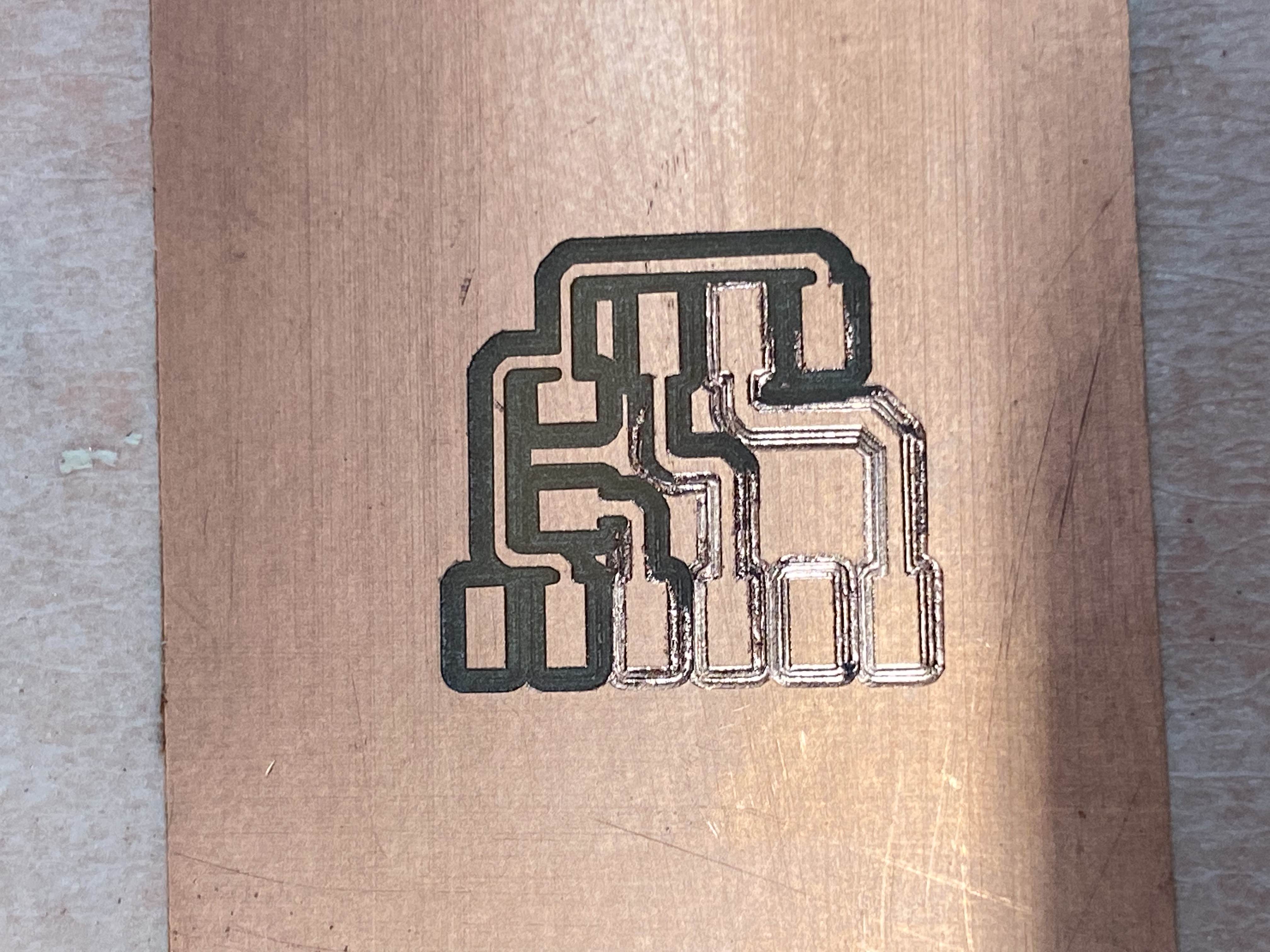
Finish inner Board
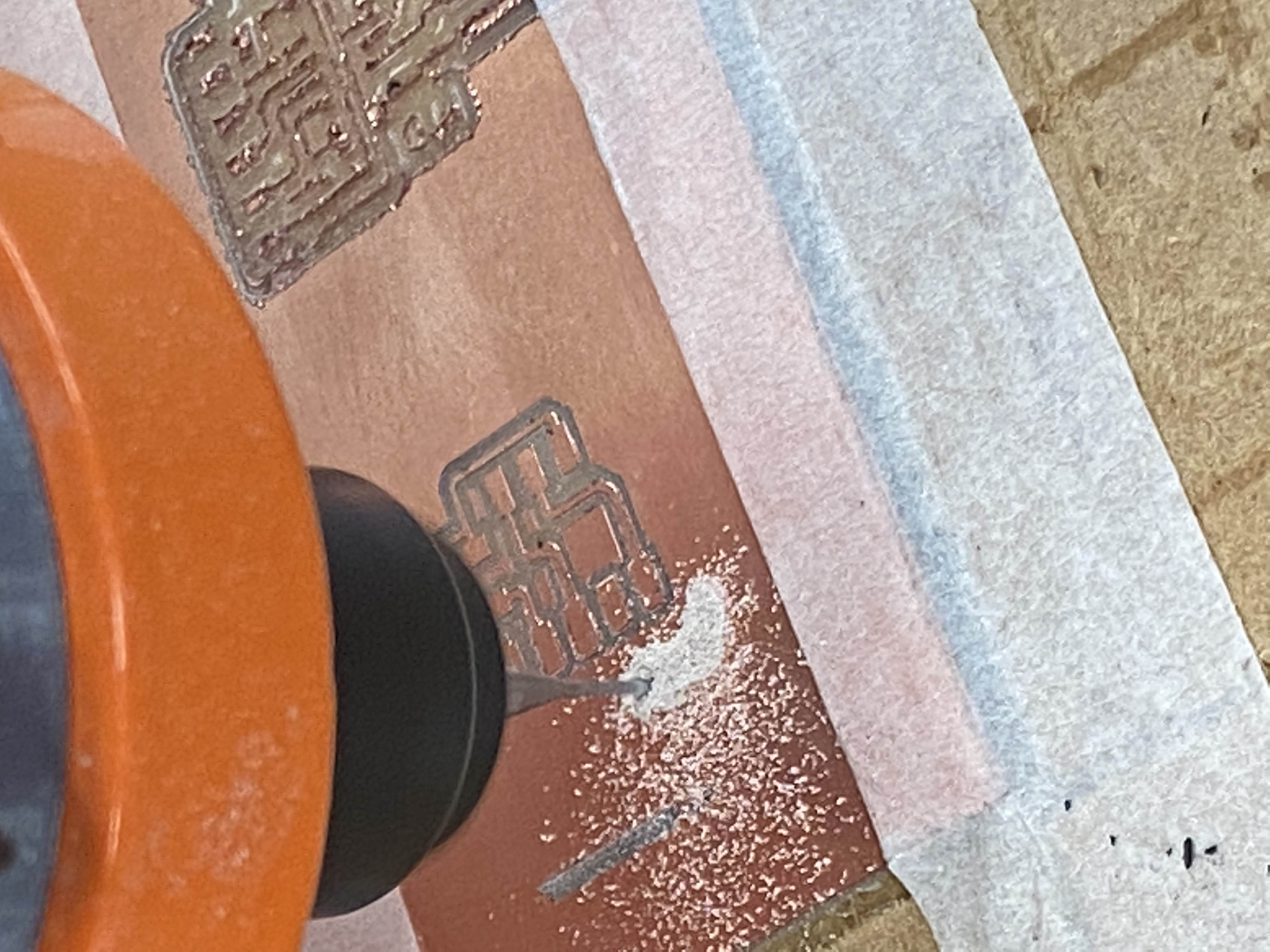
Routing the outline of the UPDI board
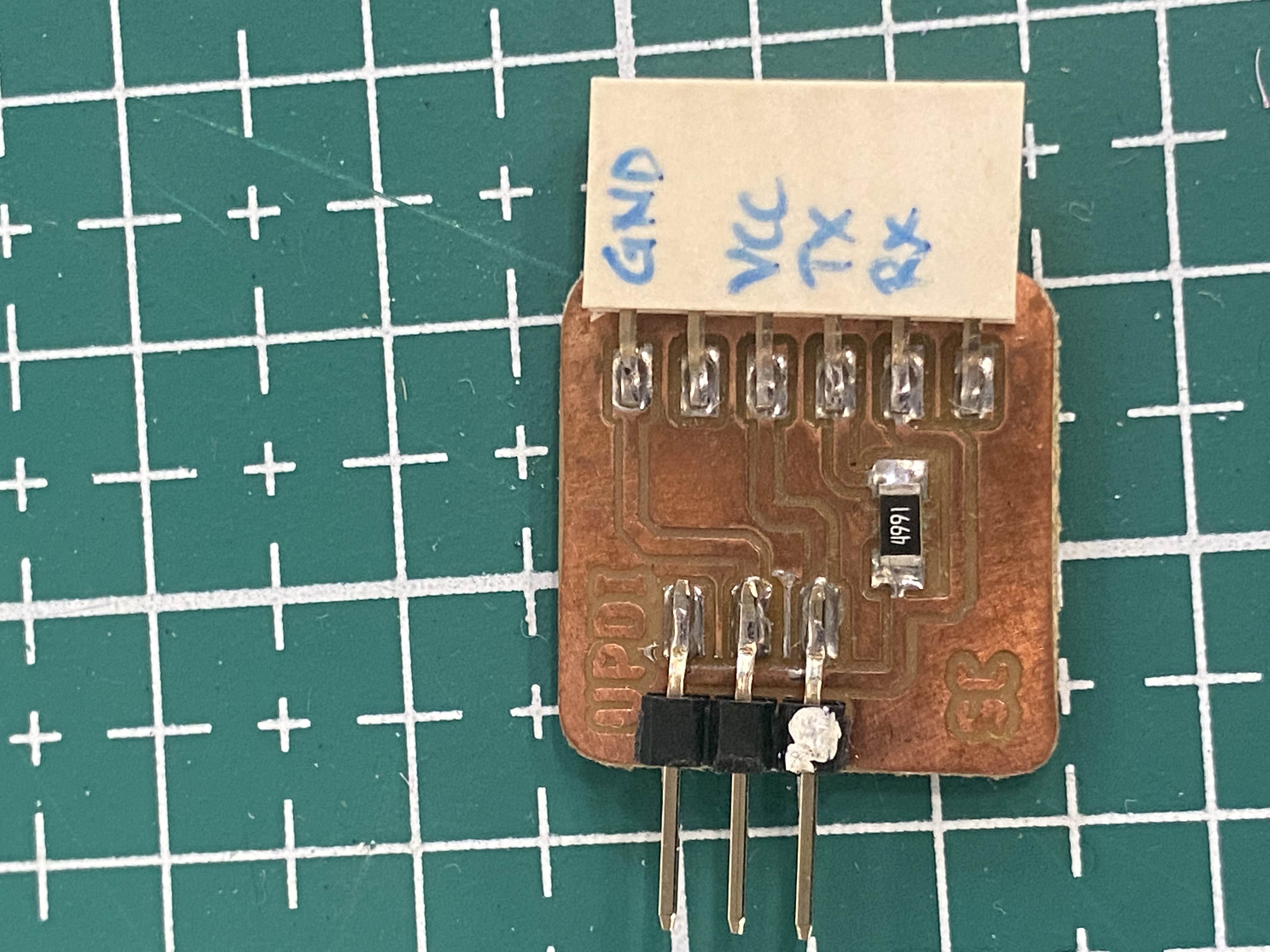
Finished UPDI board, ready for components to be soldered on
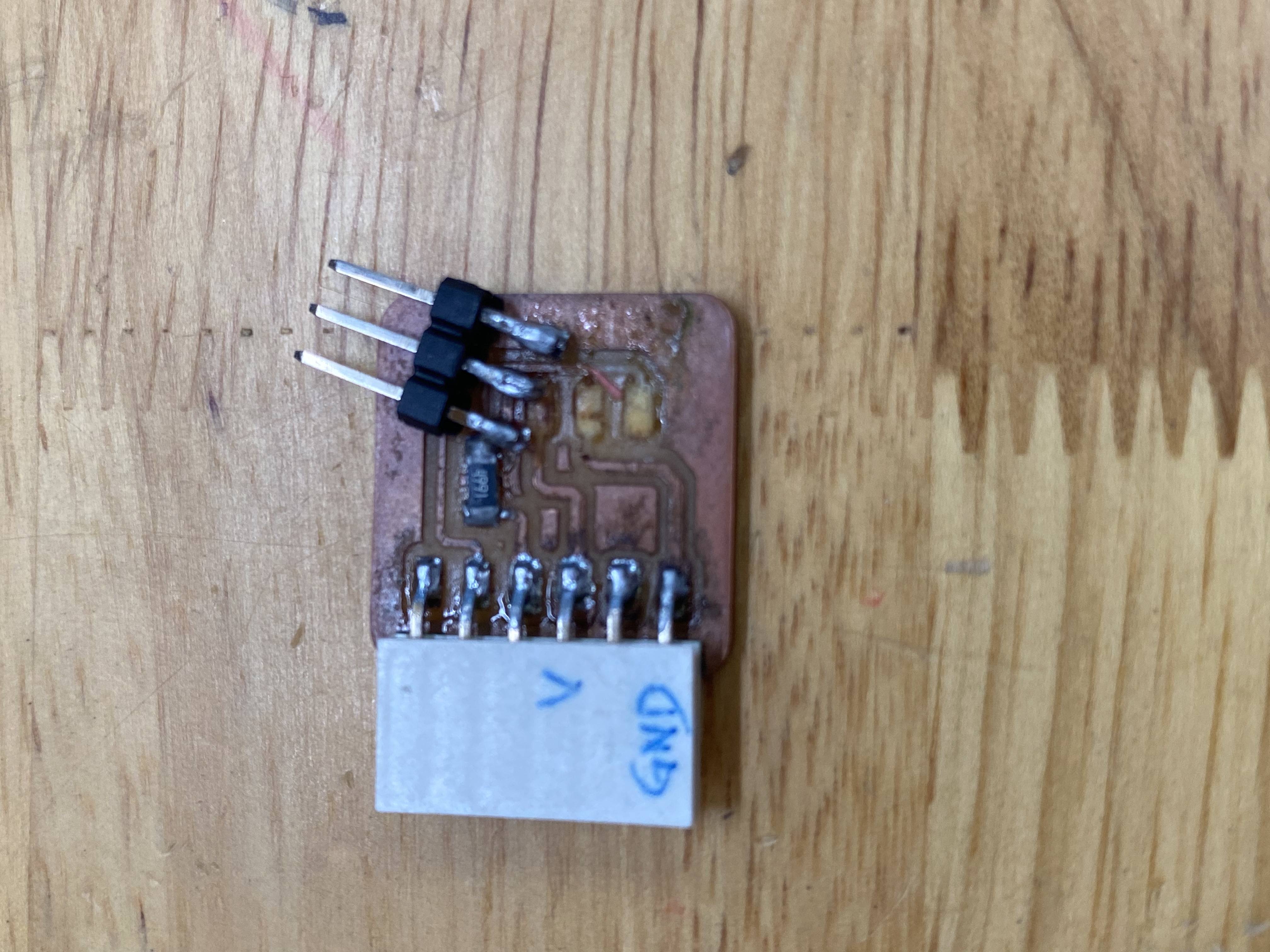
After the base board is routed, components are soldered on.
For the FTDI board, two 1 microfarad capacitors and a ATtiny412 chip was soldered on.
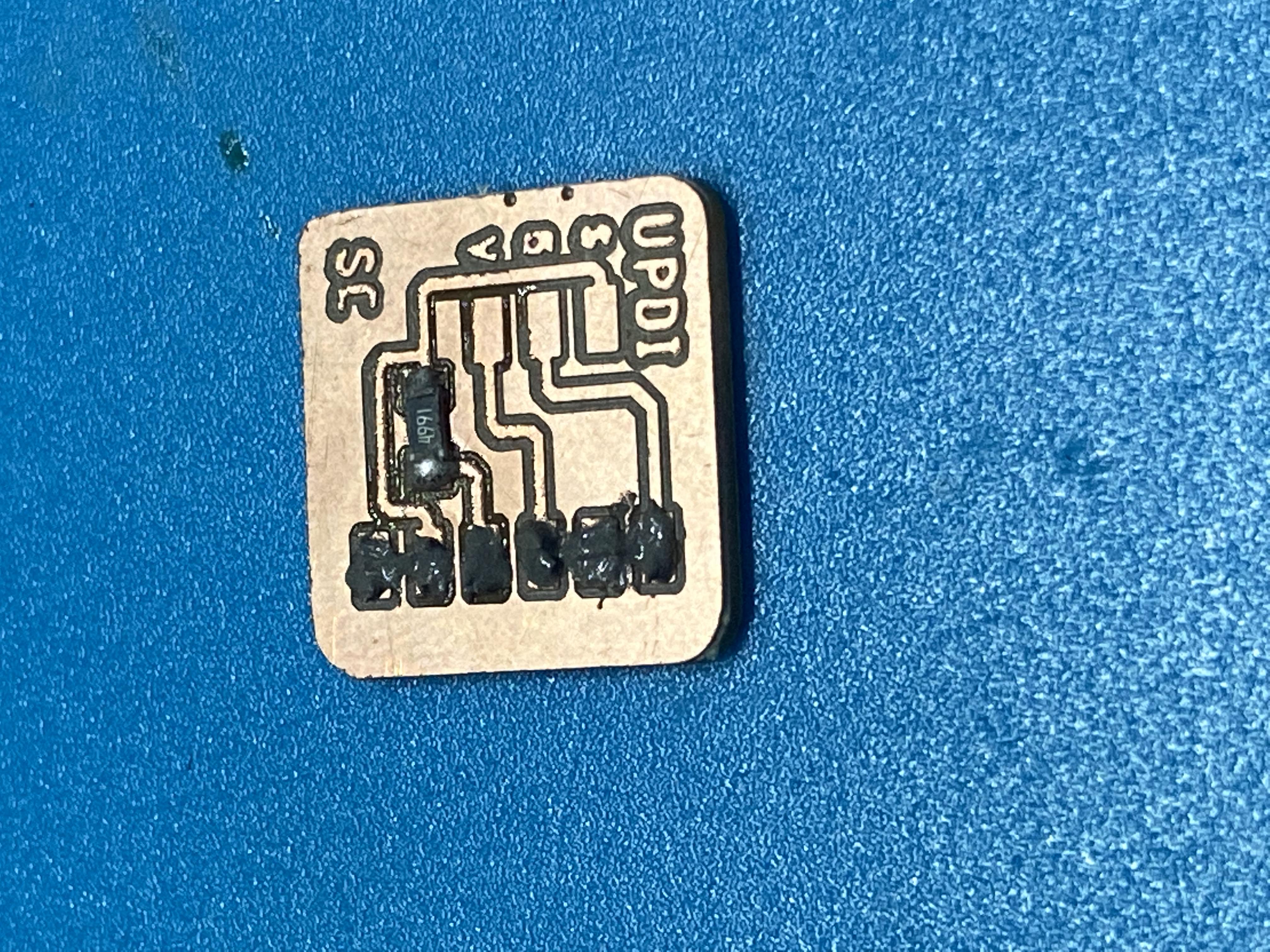
And for the UPDI board, 1 4991 packaged resistor (4.99k) was soldered on.
A series of Unfortunate Events
Unfortunatly, the header pins for the UPDI board ripped and so I had to resolder on a new pair.
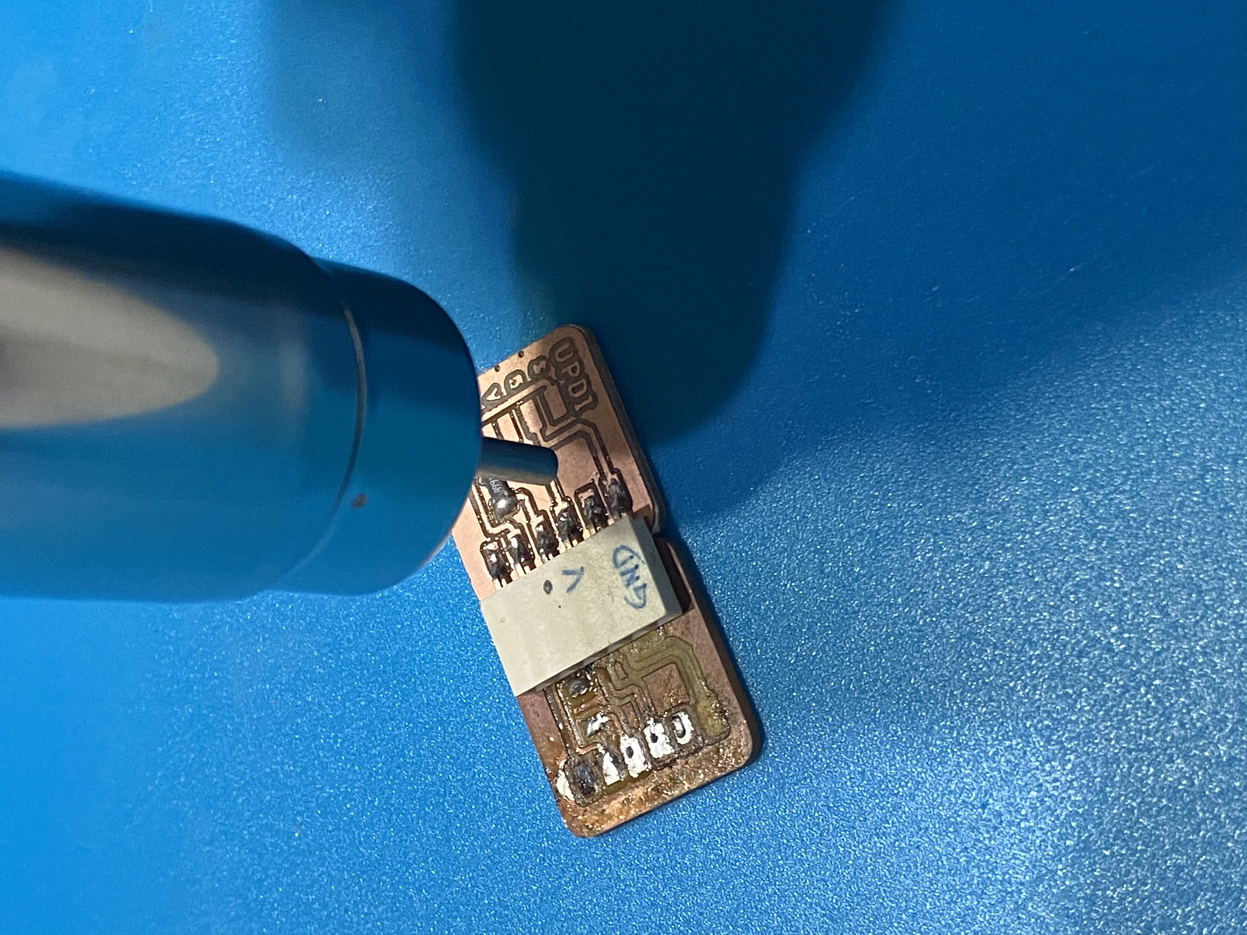
Fortuanatly, this time I used the technique of reflow soldering
New board given to me graciously by Mr Steven:
Blasting heat air directly at the solder points with a small nozzle:
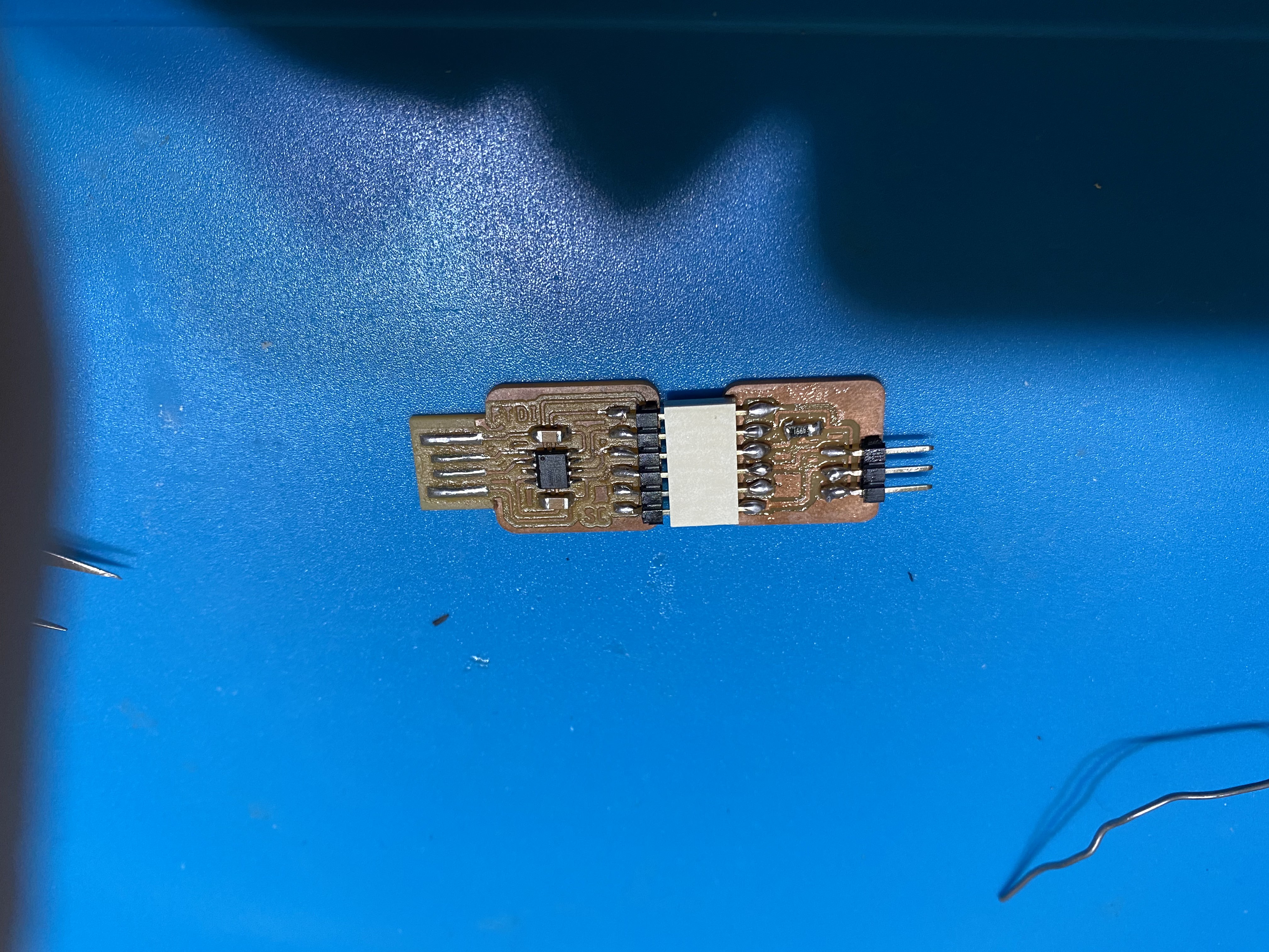
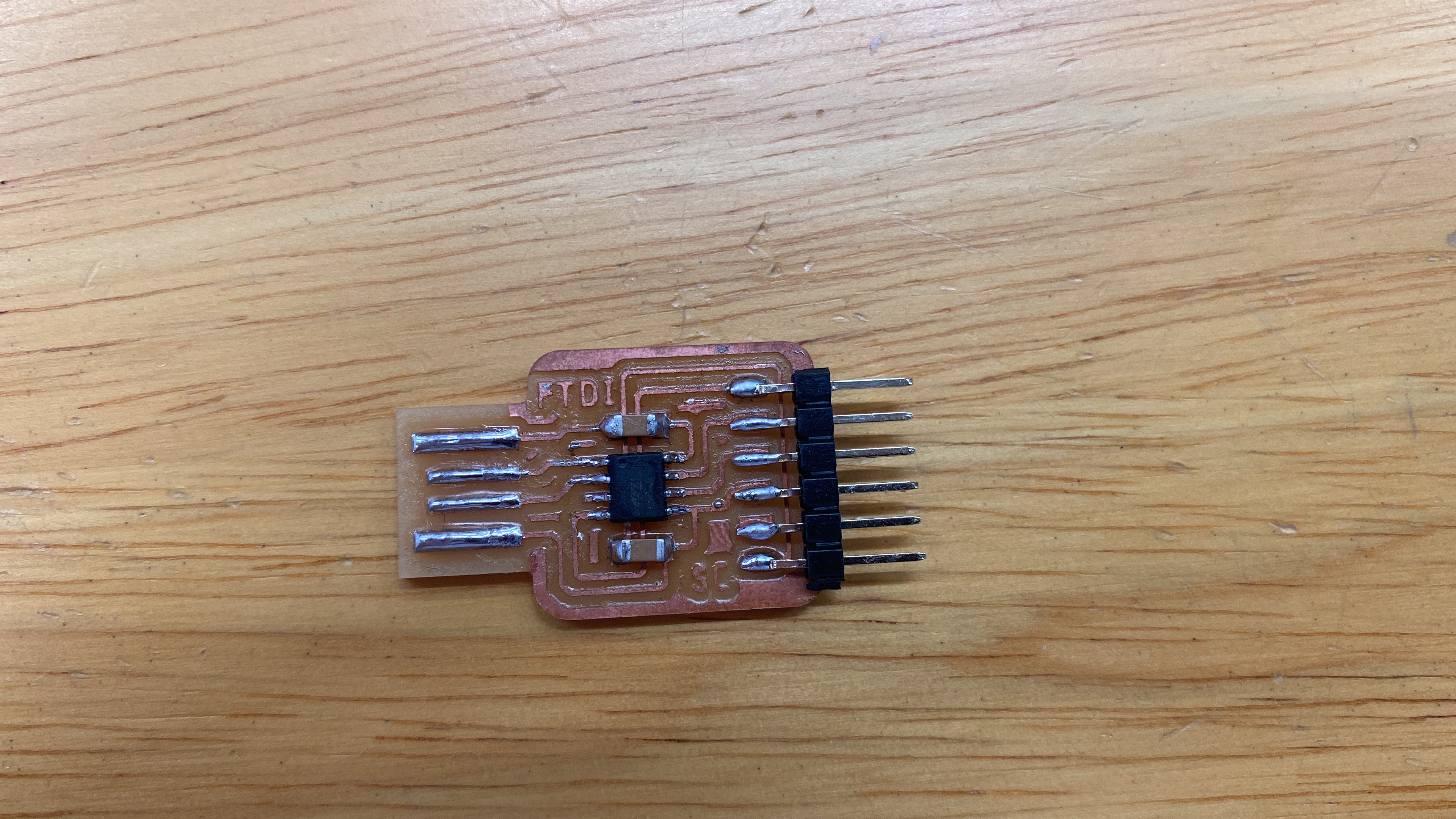
Final product of the FTDI
Final UPDI + FTDI